Shipped from abroad _ Delivery in 7 days
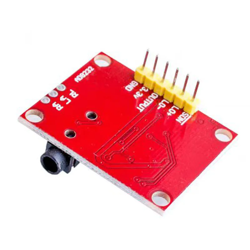
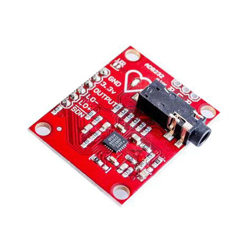
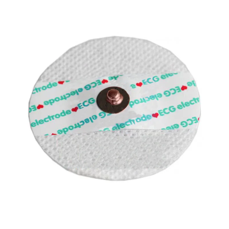
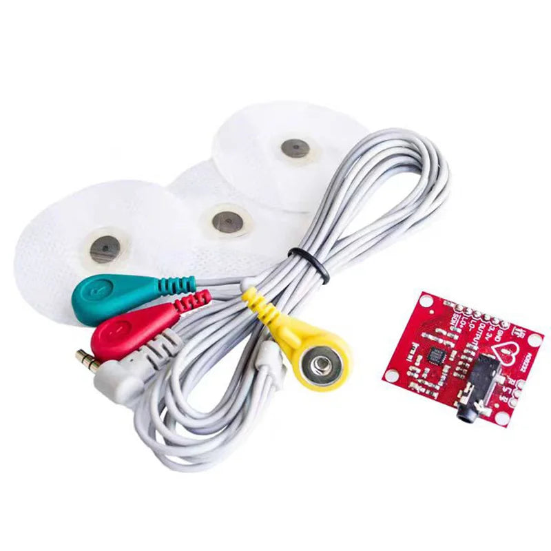
ECG AD8232 Pulse Heart ECG Kit Compatible with Duinofun Dev Boards
ECG AD8232 Pulse Heart ECG Kit Compatible with Duinofun Dev Boards
Couldn't load pickup availability
SPECIFICATIONS
Application: standard
Brand Name: PENGHEKEJI
Choice: yes
Condition: New
Dissipation Power: standard
Hign-concerned Chemical: None
Model Number: AD8232
Operating Temperature: standard
Origin: Mainland China
Supply Voltage: standard
Type: Module
is_customized: Yes
1 HPDRIVE High-pass driver output. The HPDRIVE should be connected to the capacitor in the first high pass filter.
The AD8232 drives this pin to keep HPSENSE at the same level as the reference voltage.
2 +IN Instrumentation amplifier positive input. +IN is normally connected to the left arm (LA) electrode.
3 -IN Negative instrumentation amplifier input. -IN is normally connected to the right arm (RA) electrode.
4 RLDFB Right leg drive feedback input.RLDFB is the feedback pin for the right leg drive circuit.
5 RLD Right leg drive output. The drive electrode (usually the right leg) should be connected to the RLD pin.
6 SW Fast recovery switch pin. This pin should be connected to the output of the second high-pass filter.
7 OPAMP+ Operational amplifier in-phase input.
8 REFOUT Reference voltage buffer output. The instrumentation amplifier output is referenced to this potential.
REFOUT should be used as a virtual ground for any point in the circuit where a reference signal is required.
9 OPAMP- Operational amplifier inverting input.
10 OUT Operational amplifier output. This output provides a fully conditioned heart rate signal.
OUT can be connected to the input of the ADC.
11 LOD- Lead-off comparator output. In DC lead-off detection mode, when disconnected from the -IN electrode, LOD- goes high.
LOD- is in a high state and vice versa. In AC lead-off detection mode, LOD- is always low.
Lead-off comparator output. In DC lead-off detection mode, LOD+ is in a high state when the +IN electrode is disconnected, and
Conversely, it is low. In AC lead-off detection mode, LOD+ goes high when the -IN or +IN electrode is disconnected and low when both electrodes are connected.
When both electrodes are connected, it is low.
12 LOD+
13 SDN OFF control input. Drive SDN low to enter low-power shutdown mode.
14 AC/DC lead-off mode control input. For DC lead-off mode, the AC/DC pin should be driven low.
For AC lead-off mode, the AC/DC pin should be driven high.
15 FR Fast Recovery Control Input. Driving FR high enables fast recovery mode; otherwise, it should be driven low.
16 GND Power ground.
17 +VS Power supply pin.
18 REFIN Reference voltage buffer input.REFIN (high impedance input pin) can be used to set the level of the reference voltage buffer.
19 IAOUT Instrumentation amplifier output pin.
20 HPSENSE High-pass detection input for the instrumentation amplifier.
HPSENSE should be connected to the R & C junction that sets the turn frequency of the isolation circuit.
EP Exposed Pad. Exposed pads should be connected to GND or left unconnected.